D. L. Martin has over 40 years of experience developing and manufacturing a wide range of hydraulic cylinders for a variety of applications with a focus on elevator jacks. We produce Single Stage Borehole, Holeless and Roped elevator jacks with pistons from 2.95" to 8" in diameter. These jacks can be produced in section lengths per customer requirements and can also be ordered with fully sealed PVC protection for borehole applications.
In addtion to our Single Stage jack offerings, we also produce a full range of internally sychronized 2 and 3 stage telescopic jacks. These jacks are currently offered in 2.5 and 2.75 plunger sizes.
All D. L. Martin jacks are designed and manufactured according to ASME A17.1-2013 requirements. The company is ISO 9001:2008 certified. D. L. Martin is also approved by the Canadian Welding Bureau to CSA standard W47.1 Division 3 with AWS certified welders and standards. A zero defect AQL (acceptable quality level) 1.5 inspection program is used to assure the highest quality standards attainable are maintained throughout the manufacturing and assembly processes.
Jack “bumps” when joints pass through head
Most likely cause is a tight wear band.
Request that D.L.M. send a new wear band with thickness at low limits.
Joint blended too abrupt (can be checked with micrometers, or a straight edge and feeler guages-record results)
A wear band with thickness at the low limit may help. A joint with too abrupt a blend can be corrected by filing. Filing must not remove material away from the joint.
Load ring for seal may be pinched, due to running upside down.
Check seal to make sure load ring is installed correctly. The tapered end of the ring should rest against the chamber of the actual seal.
Joint blended too deep. If this is the case, slight leakage may be noticed as joint passes through head. (Can be checked with micrometers, or a straight edge and feeler gauges-record results)
New Plunger sections may be needed if problem is severe.
Joint not blended in field. (If fingernail catches on joint, additional sanding is needed.)
Sand joint smooth with supplied sandpaper.
Ride is rough (not just at the joints)
Jack not plumb. (Jack must be plumbed using plumb wire supplied in plunger sections.)
Re-plumb using plumb wire
Load ring for seal may be pinched, due to running upside down.
Check seal to make sure load ring is installed correctly. The tapered end of the ring should rest against the chamber of the actual seal.
Tight wear band
Request that D.L.M. send a new wear band with thickness at low limit.
Jack squeals
Tight wear band
Request that D.L.M. send a new wear band with thickness at low limit. A low friction oil additive could also be tried. Schindler spec. 54605ME
Scribe lines at plunger joint do not line up.
Joint may have seized just before being fully tightened.
Lines should come within 1/8" of meeting up. If lines are past meeting up, do not back off joint (this may cause joint to loosen and come apart).
Damaged thread on plunger coupling
Dress threads using thread file designed for 8-pitch UNC thread. Tool TD338 available.
Plunger scored vertically
Plunger not plumb in cylinder, causing plunger to bind in the head.
Make sure both cylinder and plunger are plumb (at least aligned with each other).
Chip or other debris caught in head
Remove head, check oil for contamination (use pump and filter if necessary as well as magnet to fish for chips). Chips may come from field installed hatch pipe and fittings, always clean pipe thoroughly before installing.
Wear band too thin (correct thickness is .124"/. 127")
Replace wear band
Plunger joint was run through head prior to field blending.
Always blend joint before running jack.
Plunger joint was run through head prior to field blending.
If damage is not severe, plunger may be repaired by smoothing with sandpaper, if scoring is deep, new plunger section(s) will be needed, as well as a new sleeve and seal kit.
Jack is too long.
Ordering error
Order a stop sleeve to reduce overtravel.
Jack is too short.
Ordering error
First, check to see if a plunger extension would solve the problem. (Need to be sure over- travel and undertravel would still be sufficient.) If extension won't work, then either a new jack section (for multi-pc) or a new jack (for a one-pc) must be ordered.
Banging noise (always occuring at same point in travel every trip)
Plunger plug hitting cylinder joint.
Rotate plunger to locate "flat spot" on plunger plug next to cylinder wall.
Possible Cause: Plunger plug hitting cylinder joint.
Solution: Make sure plunger and cylinder are both plumb, and in alignment with each other.
Cylinder coupling can not be removed from jack shipping ass'y.
Threads seized
Cut coupling off. Request new coupling from D.L.M.
Cylinder coupling doesn't turn freely when assembling sections.
Split ring sections may not have proper curvature.
Slide coupling away from joint, and test fit split ring sections against the cylinder wall (in their normal location) if the split ring does not fit snugly along its entire length, its shape may be corrected by tapping with a mallet.
If the condition is too severe to be corrected in the field, request D.L.M. to send a new pair of split ring halves.
Damaged thread
If coupling can be backed off, do so, and repair thread with a thread file. Also inspect for debris which may be contributing to the problem.
If coupling seized up when partially engaged, it should be cut apart to remove. in this case, request D.L.M. to send a new coupling.
Possible incorrect assembly
See orange warning label near cylinder joint - gap between male and female couplings should be about 1/8" and wide yellow painted line segments should line up within 1/2" when fully tightened.
Mounting feet in wrong location.
Jack ordered for incorrect pit depth.
If feet are located to high on cylinder, an additional set can be welded on in the field by a certified welder. In this case order new feet and gussets from D.L.M.
If the current feet are in a location which would prevent new feet from being welded on correctly, the field may choose to use a spacer block between the footer channel and the feet.
If the feet are too low on the cylinder, they will need to be removed by grinding, before welding new feet on.
Unsure how stop ring is installed on plunger.
Possible stop ring installation error.
The purpose of the stop ring is to limit current travel. typically it is to be located at the lowest plunger joint, and is sometimes used together with a stop sleeve which further limits travel.
After determining which joint the stop ring should be placed at, slip the ring over the male coupling at that joint so that the 15 ° bevel on the underside of the ring matches the 15 ° bevel on the plunger.
The mating plunger section can be lowered into position and assembled with the stop ring sandwiched between the two sections.
Difficulties assembling the 300A plunger joint.
Nut installed incorrectly.
Check that the nut cannot be rotated in the female coupling. also check that the nut cannot be pushed up into the plunger more than about 1/16". Call 800 or 888 number stated on the jack if either of the two tests above indicate problems.
Vibrating noise in the car. Vibrating noise at leveling speed, up or down.
1. Leveling speed is too low. 2. Oil viscosity is too low. 3. Oil temperature is high. 4. Guide arms tight on the rails.
1. Adjust. 2. Find means to reduce the temperature. 3. Add anti-chatter additive. exp max glide. make sure additive is safe for o-rings.
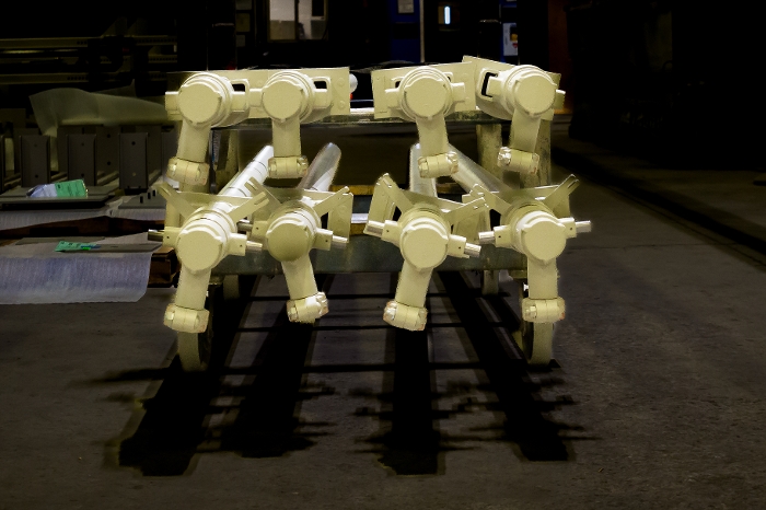
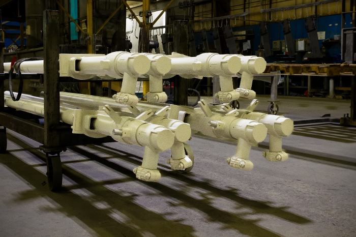
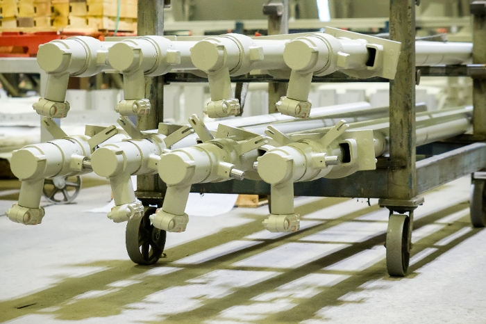
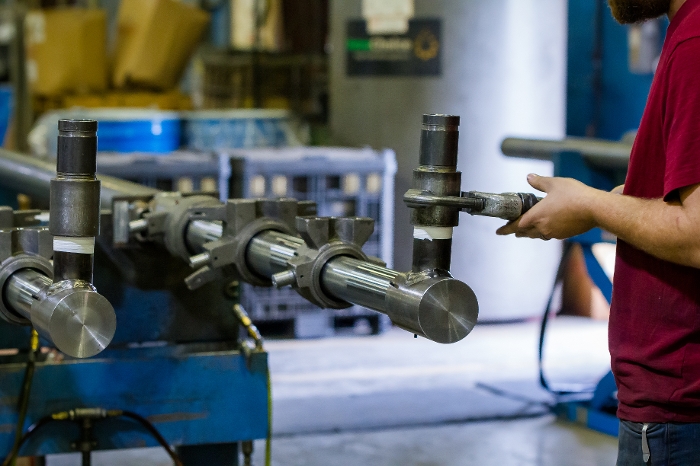
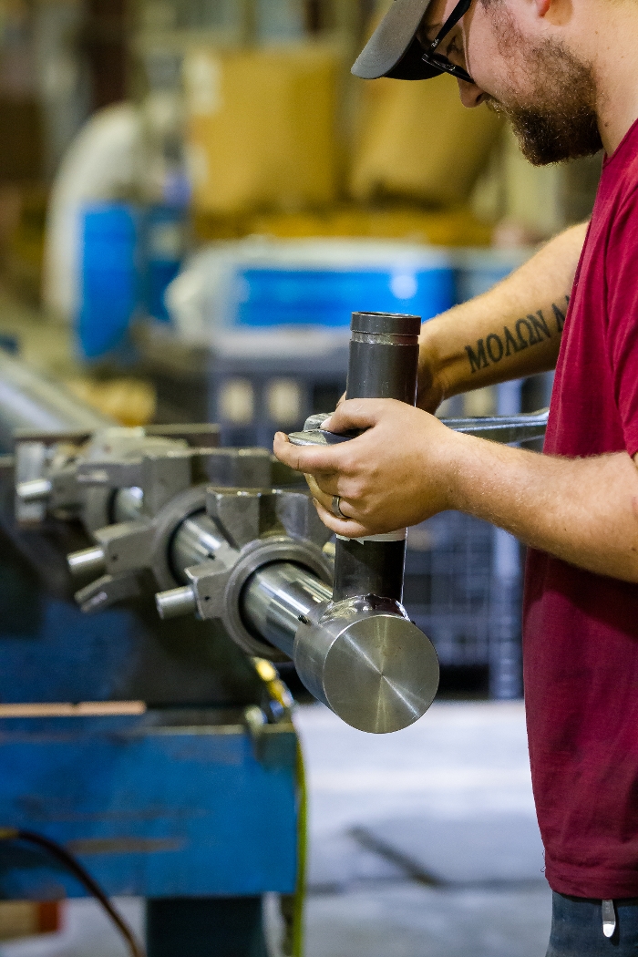
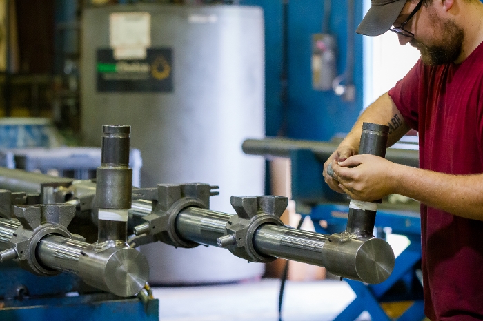
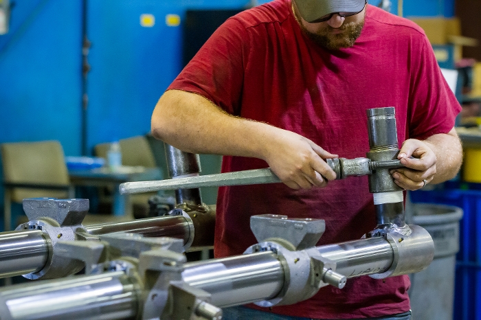
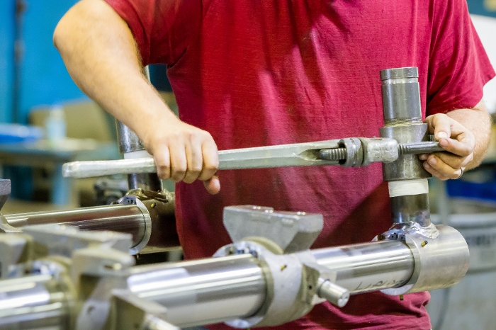
Hydraulic Photos